Comparing Safety Instrumented Systems (SIS) Transmitter, Switch, & Hybrid(PDF)
In many process industries risk reduction has been a driving requirement to increase safety and decrease equipment failures. Over the last 50 years approaches to controlling processes have changed, both in terms of technologies, but also in terms of risk reduction strategy.
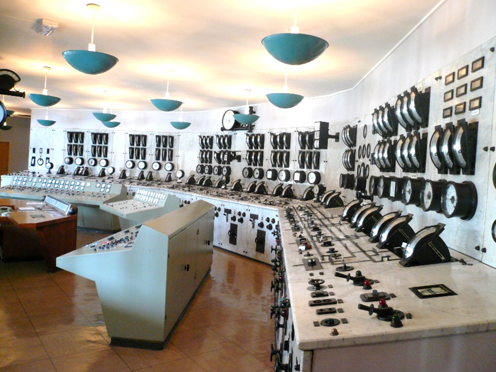
Control and Instrumentation systems began with simplistic controls which operated through either pneumatic signals or hardwired electrical signals paired with the use of relays or solenoids. These early systems had clearly defined fault/error/alarm conditions that were displayed in annunciator light panels and/or through chart recorders.

Figure 1
Pre-DCS/SCADA era Control Room
With the onset of programmable logic, the landscape changed from deterministic failure states to indeterminate failure states. More precisely, these indeterminate failure states are specific to safe operating modes of the system. Programmable logic systems can be very complex making it virtually impossible to determine or predict a specific failure state. Some errors can be introduced by the user and be programmed-in or attributed to design, causing faults that should not normally occur. Likewise, systems can have implementation errors that contribute to non-safe failure modes. As
system complexity increases so does the likelihood of undiagnosable failure states and the difficulty of predicting specific failure actions.
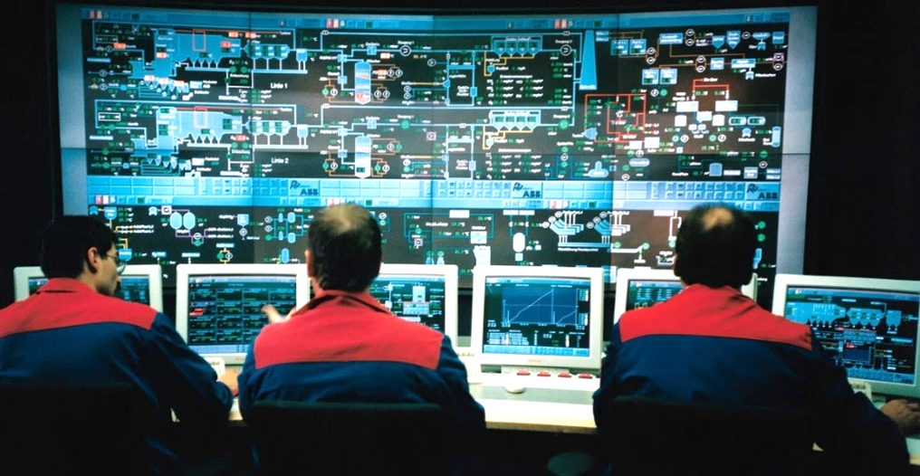
Figure 2
DCS Control Room
In an attempt to address the ever-growing complexity of systems and lack of deterministic failure states from faults, the Instrument Society of America (ISA) released the standard ISA S84 in 1996. This standard was adopted into the IEC standard IEC 61511 in 2003 Functional Safety – Safety Instrumented Systems For the Process Industry. In actuality, safety systems are governed by the standards of both
IEC 61508 and IEC 61511.
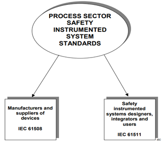
Figure 3
IEC 61508 & 61511
IEC 61511
IEC 61511 provides the necessary guidance to design Safety Instrumented Systems (SIS) with Safety Instrumented Functions (SIFs). The SIF is the mechanism used to drive the system to a safe condition. The scope of this standard breaks down into two ideas: the SIS Safety Lifecycle and Safety Integrity Levels (SILs).
The SIS Safety Lifecycle is a methodology that considers all relevant overall, Electrical, Electronic, Programmable Electronic (E/E/PE) and software as a framework to systematically deal with activities necessary to ensure functional safety for the E/E/PE safety-related systems. Safety life-cycle management starts with a safe process design. In many instances, this approach is not enough and may require protective systems to help mitigate risks. For example, an overpressure situation may occur even though a pressure regulator is installed in the system. An additional layer of safety may be to include a rupture disk to provide pressure relief if equipment failure of the regulator were to occur.
IEC 61508
On the other hand, IEC 61508 provides the necessary guidance to design products that will be used in Safety Instrumented Systems (SIS), which is done by following the product safety lifecycle.
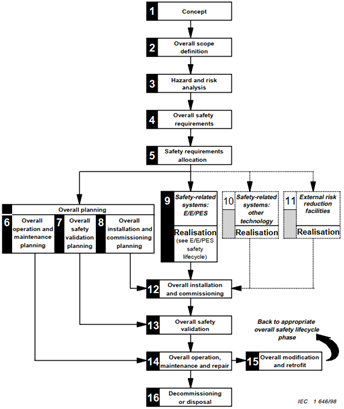 IEC 61508 defines the product safety lifecycle shown in this flowchart. As seen in Figure 4, good practice in designing an SIS includes performing a process hazard and risk analysis. From this review, safe designs will typically incorporate a layers of protection model to prevent risk and ensure the occurrence of unexpected event conditions result in safe states. For our discussion, we will focus on IEC 61508 as it relates to SIL and its application specific to switches, transmitters or hybrid switch-transmitters, which are a combination of both devices.
Figure 4
Product Safety Lifecycle
SIS Design
As one might expect, the SIS design drives the requirements of the components selected for use in the overall system. The SIS components consists of instrumentation, final elements, and logic solvers. These three devices provide the SIF used to inhibit hazardous events from occurring by driving the system into a safe state when designed limits have been breached. Each SIF will have an appointed SIL based upon the required risk reduction necessary to achieve this safe state. The SIL is a measure of the SIF which is expressed as Probability of Failure on Demand (PFD); as the PFD is reduced the SIL level will improve.
The System SIL is driven by several factors that contribute to the overall rating.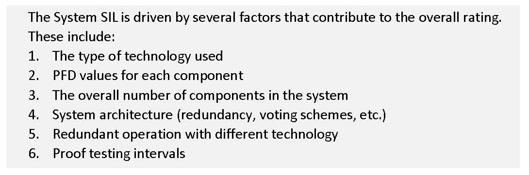
Proof testing verifies that the system is working as expected. The intervals for proof testing directly impact the PFD calculation of the overall system and consist of all elements in the SIF. Individual components in the system do not have a SIL, as it applies to the overall system; however, many products are listed as being SIL rated. This is helpful for system designers as it allows them to identify instruments compatible for use in a system with a given SIL rating.
So, when given the situation to select a transmitter, switch or a combination what makes the most sense?
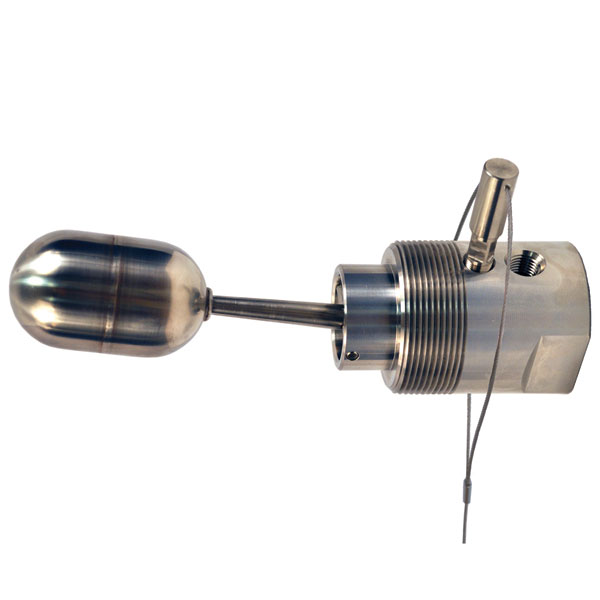
The Switch
For simplistic control, a switch is very basic element that can used in combination with a final element and/or solver. In some cases, the switch acts as both the solver and instrument which then drive a response from the final element. Switches have advantages when speed is of the most important criteria. When switches are used as both the solver and the instrument, redundancy improves the SIF in case of inadvertent failure. Most complicated systems use switches as a backup technology and as a redundant source of information to prevent unsafe conditions.
The Transmitter
Conversely, transmitters provide a more sophisticated level of risk management. Typically, Transmitters publish their findings to the solver in the system. When a switch is acting as both the instrument and solver it is more at risk; however, 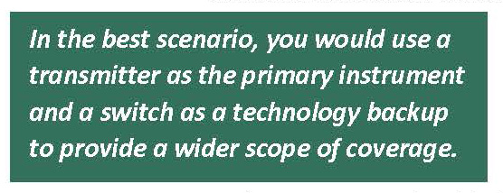 using a transmitter eliminates the solver from the possible failure mode of one device creating unsafe conditions since the solver and transmitter are two separate devices. Transmitter prices have come down over the years and can reasonably compete with switches; however, that doesn’t necessarily remove the need for or use of switches. Transmitters can fail in many ways that impact the safety function such as drifting values, failure of readings, slow response times, inadvertent noise, etc. These conditions drive the need for redundant backup, specifically in the form of a technology backup.
The Hybrid Device
Hybrid instruments consist of both a discrete and an analog output like a combination switch-transmitter. Just like in the case of the switch, the hybrid device is also acting as a solver for the SIF in some situations. A hybrid device provides a lower cost of ownership for the SIF in that it provides redundant measurements. For most systems, this approach is very cost effective; however, in certain scenarios, the solver and instruments should all be separate devices to help prevent unwanted faults.
In the best scenario, you would use a transmitter as the primary instrument and a switch as a technology backup to provide a wider scope of coverage. Each device would be powered from separate voltage sources and would have redundant backup (e.g. having two transmitters and two switches each for one specific SIF). Additional redundancy can be added for even more protection, with voting schemes implemented in the solver to help determine that the instrumentation is trustworthy. Ultimately, the type of device used depends upon the product system lifecycle shown earlier. A hazard analysis should be reviewed to understand what makes the most sense for the end-user application SIF, as each SIF will ultimately determine what provides the best advantage.
References
Figure 1: Pre-DCS/SCADA era Central Control Room
“Kontrollrom Tyssedal” by David40226543 / CC BY-SA 3.0
Figure 2: DCS Control Room
“Leitstand 2” by Steag / CC BY-SA 3.0
Figure 3: IEC 61508 & 61511
International Electrotechnical Commission. Functional safety – Safety instrumented systems for the process industry sector (IEC 61511 Edition 2.1 2017-08)
Figure 4: Product Safety Lifecycle
International Electrotechnical Commission. Functional safety of electrical/electronic/programmable electronic safety-related systems (IEC 61508 First Edition 1998-12)
Michael Bequette, P.E. – VP of Engineering SOR Controls Group
 Michael Bequette has dual undergraduate degrees in Electrical Engineering, and Theoretical Physics from Kansas State University. He has a Master’s Degree in Electrical Engineering from the University of Kansas, and a Master of Business Administration from Park University. Michael has 29 years of experience in the oil and gas space, as well as aerospace, glass, pulp and paper, and water/wastewater. Michael is a licensed professional engineer in multiple states, holds 4 patents for fiber optic product development and capacitive fault location and is a senior member of IEEE.
Matthew Giunta – Marketing Manager SOR Controls Group
 Matthew Giunta is a graduate of the University of Kansas with a Bachelor of Science in Chemical Engineering. Before coming to SOR Controls Group he worked as a Field Engineer cementing
wells in the Permian Basin and as a Clinical Research Technician processing biological samples for investigational drug studies. Matthew is a Marketing Manager at SOR Controls Group and is
responsible for overall product line management. He has also served as a Product Manager and an Inside Sales Engineer.